REFERENCE DESIGN RELEASE: CLOSED CYCLE, SEALED GEOMETRY, 19 PUBLISHED CHECKS.
PROJECT 001: PROPULSION
Orion 13.3 kN Turbojet
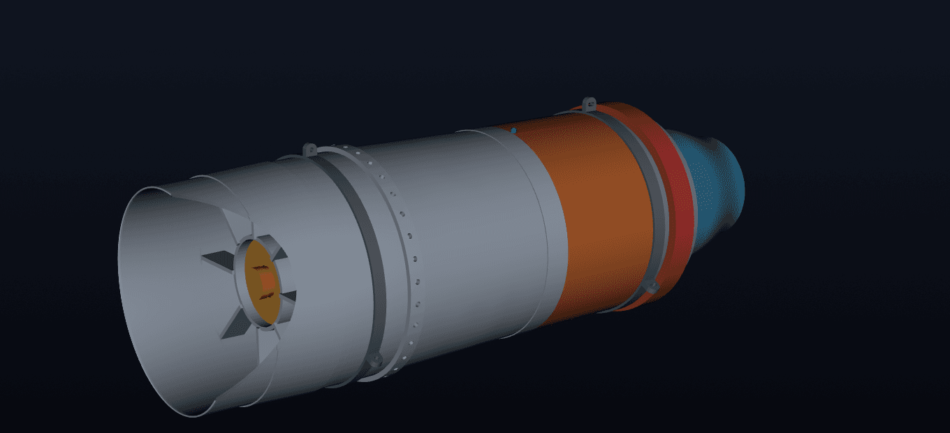
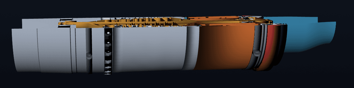
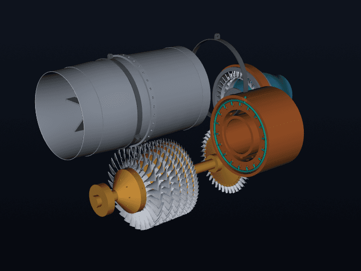
Not a rendering: the release geometry itself, streamed to your browser. Orbit the cutaway and look straight down the six-stage core.
- ARCHITECTURE
- Single-spool turbojet
- COMPRESSOR
- Six-stage axial blisk
- COMBUSTOR
- Annular
- NOZZLE
- Fixed converging
The check matrix: 19 declared thresholds, 19 measured values
Each line carries the value the closed design returned and the requirement it was held against. Both numbers, every time. A pass with a hidden threshold proves only that somebody wrote the word pass, so the thresholds are here whether they flatter the result or not. Read the TSFC line the way a propulsion engineer would: the ceiling was 100 and the cycle closed at 99.2591, a margin of 0.74 percent rather than 20.
| # | CHECK | MEASURED | REQUIREMENT | Verdict |
|---|---|---|---|---|
| 01 | Sea-level static thrust meets the no-sacrifice target | 13.3384kN | ≥ 12.35 | pass |
| 02 | Sea-level static TSFC meets the redesign target | 99.2591kg/(kN·h) | ≤ 100 | pass |
| 03 | Advanced-construction dry mass meets target | 165.2018kg | ≤ 170 | pass |
| 04 | Conventional all-metal fallback stays in band | 209.0000kg | 190 - 210 | pass |
| 05 | Design airflow closes the reduced-annulus target | 16.6521kg/s | 16.5 - 17.0 | pass |
| 06 | Engine length stays in the redesigned envelope | 1380.00mm | 1350 - 1400 | pass |
| 07 | Maximum diameter stays in the redesigned envelope | 436.00mm | 420 - 445 | pass |
| 08 | Positive net thrust at every simulated point | 5010.44N | > 1000 | pass |
| 09 | Turbine closes the compressor shaft-power balance | 7×10⁻¹⁰W | < 1 | pass |
| 10 | Six-stage station table closes the solved compressor exit | 4×10⁻¹⁶rel. | < 1×10⁻⁹ | pass |
| 11 | Nozzle throat geometry matches the design solution | 0.0000% | < 0.5 | pass |
| 12 | Compressor stage pressure ratio is credible | 1.4913ratio | 1.20 - 1.70 | pass |
| 13 | Rotor tip speed stays in transonic precedent range | 435.42m/s | ≤ 455 | pass |
| 14 | Relative compressor tip Mach stays bounded | 1.3806Mach | ≤ 1.40 | pass |
| 15 | Compressor discharge temperature below concept limit | 610.35K | < 650 | pass |
| 16 | Internal quasi-1D stations remain subsonic | 0.5011Mach | < 0.85 | pass |
| 17 | Fuel-air ratio stays in gas-turbine operating range | 0.0221ratio | 0.01 - 0.04 | pass |
| 18 | Design nozzle is choked | true | true | pass |
| 19 | Spool speed implements the redesigned operating point | 21000rpm | 21000 | pass |
Six of these lines are calculation verification rather than agreement with a measurement: the shaft power balance, the station table closure and the nozzle throat check confirm the solver closed its own algebra, which is real evidence and a different kind of evidence from validation. No line here is a comparison against measured hardware data, because none was taken. That distinction is the reviewer's job, so it is stated here rather than left for them to find.
The gas path, station by station
Gas path: ten solved stations
The hub line is computed from each station's published flow area, so the section and the numbers cannot disagree.
Across the combustor: station 3.6 to 4
Point summary: Sea-level static
- NET THRUST
- 13.34 kN
- TSFC
- 99.3 kg/(kN·h)
- AIR MASS FLOW
- 16.65 kg/s
- FUEL FLOW
- 0.368 kg/s
- COMPRESSOR-FACE MACH
- 0.450
- NOZZLE
- choked
Read from simulation/flow_stations.csv and simulation/operating_points.csv in the release package. The nozzle throat is solved once at the design point and held fixed; the compressor-face Mach at altitude is whatever satisfies that fixed capacity.
Design point
- Sea-level static net thrust
- 13.34 kN
- Specific thrust
- 801.0 N·s/kg
- Air mass flow
- 16.65 kg/s
- Fuel flow
- 0.368 kg/s
- TSFC
- 99.3 kg/(kN·h)
- Overall pressure ratio
- 11.00 : 1
- Per-stage pressure ratio
- 1.491 : 1
- Compressor discharge temperature
- 610.4 K
- Turbine inlet temperature
- 1320 K (1046.8 °C)
- Compressor shaft power
- 5.392 MW
- Nozzle exit velocity
- 574.9 m/s
- Nozzle throat area
- 0.03965 m²
- Rotor tip speed
- 435.4 m/s
- Relative rotor-tip Mach
- 1.381
B-rep CAD assembly: AP214 STEP
| FILE | SOLIDS | VOLUME | STATION |
|---|---|---|---|
orion_engine_assembly.step Named, coloured multi-body assembly | 561 | 24,430 cm³ | 0 - 1380 mm |
compressor_6_stage.step IGV plus six blisk rotor/stator stages | 398 | 6,505 cm³ | 188 - 766 mm |
annular_combustor.step Perforated annular liner | 77 | 2,301 cm³ | 788 - 1040 mm |
turbine_stage.step Nozzle guide vane and rotor | 77 | 2,249 cm³ | 1030 - 1176 mm |
structure_and_nozzle.step Shaft, centerbodies, gimbal mounts, nozzle | 9 | 13,376 cm³ | 0 - 1380 mm |
outer_casing_full.step Ø420 core casing | 1 | 9,674 cm³ | 0 - 1170 mm |
internal_flow_domain.step Solved gas path as a solid | 1 | 117,185 cm³ | 0 - 1380 mm |
Regenerated from the same parametric dimensions as the mesh pipeline. Opens in any AP214-capable CAD system.
The same method ships as a service: aircraft design verification covers the declared-threshold check matrix, and the engine cycle deck is how the design point gets closed.
Your brief next
Want a package like this for your brief? The intake takes under five minutes.
TYPICAL D2 FEE · $28,000-$48,000