CAPABILITY 02: PROPULSION
Engines integrated into the airframe they live in.
Genesis Ventures closes engine airframe integration for small turbojets: inlet, engine face, ducts, bay clearance and the mass-balance coupling through the host airframe. The Orion/T1 pairing is the published proof. Cycle selection and performance decks sit with our cycle analysis capability.
Scope
What an engagement in this capability covers, scoped against your mission profile at the requirements gate.
- Engine airframe integration: inlet, engine face and duct definition against the host
- Engine-bay installation: clearance verified in the sealed airframe geometry
- Mass-balance coupling: engine mass and CG carried through the airframe budget
- Cycle selection and altitude × Mach decks via our cycle analysis capability
Engine airframe integration starts at the inlet path.
The airframe has to deliver the mass flow the engine cycle expects at each mission condition. Orion publishes 16.65 kg/s at sea-level static and 7.08 kg/s at 10 km / Mach 0.70. Those anchors give inlet capture and duct sizing a direct connection to the engine deck.
The T1 configuration uses a blended chin inlet and a hollow, area-scheduled S-duct to reach its aft-mounted engine. The compressor-face Mach values in the published deck run from 0.450 to 0.501 across the three operating points. That interface belongs in the concept definition so propulsion and airframe reviewers work from the same station.
Concept integration fixes the inlet location, duct architecture, engine-face station and the performance anchors carried into the aircraft model. Detailed distortion analysis under maneuver and later inlet testing build from those declared interfaces.
Installation geometry carries clearance into mass and balance.
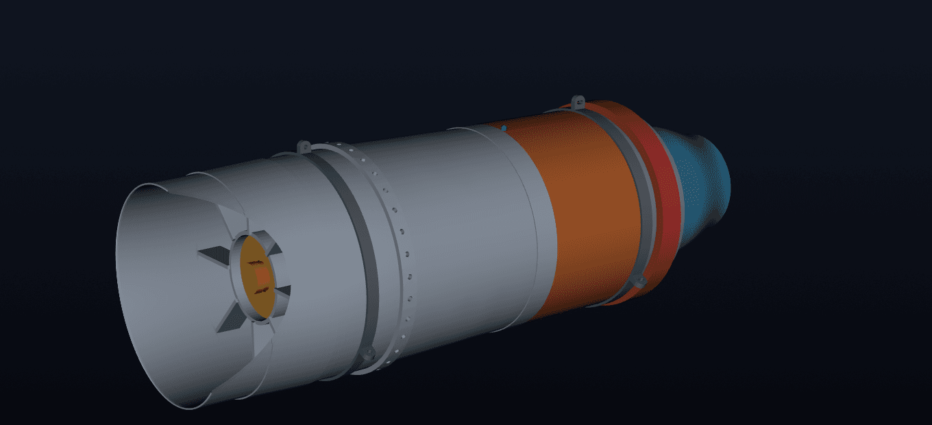
Orion-T1 locates the engine face at x = 2,900 mm and the nozzle exit at x = 4,280 mm. The sealed geometry reports 15.55 mm radial, verified engine-bay clearance. These are measured locations and clearance inside the published concept model.
The engine enters the vehicle mass budget at 165.2 kg. The complete budget closes at 696.5 kg, with the center of gravity at 2,497 mm (49.0% length) and a static margin of 0.130 MAC. Installation has therefore moved through the balance solution as well as the CAD volume.
That coupling keeps a propulsion change visible to the host aircraft. A new engine mass, mounting station, duct route or fuel allocation reopens clearance and balance in the same release. The handoff is a set of linked geometry and model entries with their checks attached.
The engine deck is checked inside the aircraft model.
The integrated concept carries full altitude and Mach thrust and TSFC tables from the engine cycle equations into the 6-DoF aircraft simulation. The published T1 receipt states that both the aircraft and engine deck are generated from the design files, while wetted areas come from the CAD solids.
The fuel and thrust anchor card gives the correlation result directly: TSFC 129.0 vs cycle 128.9; thrust error 2.3% and 4.1%, against the expectation within ±10% of the cycle model. This receipt identifies the model condition, the expected corridor and the measured simulation response.
A buyer receives the installation definition, the engine performance handoff and the verification trail for the integrated concept. Thermal analysis, detailed inlet distortion work, control hardware and physical test evidence advance under later scopes with their own requirements.
Published Orion and T1 integration anchors
The reference values tie the cycle deck to the T1 installation model. Customer integration work uses the host aircraft and engine selected in its brief.
| MEASURE | VALUE | BASIS |
|---|---|---|
| Sea-level static air mass flow | 16.65 kg/s | Orion design point |
| 10 km / Mach 0.70 air mass flow | 7.08 kg/s | Orion off-design deck |
| Compressor-face Mach | 0.450 to 0.501 | Three published operating points |
| Engine face station | x = 2,900 mm | T1 installation geometry |
| Nozzle exit station | x = 4,280 mm | T1 installation geometry |
| Engine bay clearance | 15.55 mm radial, verified | T1 clearance check |
| Fuel & thrust anchors | TSFC 129.0 vs cycle 128.9; thrust error 2.3% and 4.1% | 6-DoF simulation |
What you get
Each gate ends with a customer-facing deliverable. The full five-gate sequence is on how we work.
- 01Installation geometry with verified clearance in the host airframe
- 02Inlet and duct definition sized to the engine face
- 03Mass and CG entries that close the airframe balance budget
- 04Verification receipts: every figure checked against a declared threshold
Proof: Orion
- 15.55 mm engine-bay clearance, verified in the T1 airframe
- Blended chin inlet, hollow area-scheduled S-duct
- Engine face at x = 2,900 mm; nozzle exit at x = 4,280 mm
Technical reading for this capability
Buyer guides and checklists tied to the same published evidence.
- Turbojet and airframe integration checklist
Work the inlet, engine face, bay, balance and exhaust interfaces in order.
- Orion-T1: engine model to airframe
The published handoff from Orion cycle data to the T1 concept model.
- Compare small-turbojet design proposals
Normalize installed and uninstalled conditions before comparing engines.
An installation definition with the evidence linked.
Engine airframe integration delivers inlet and duct definition, declared interface stations, CAD clearance checks, mass and balance entries, plus the performance deck used by the aircraft model. The T1 correlation receipt comes from scripted 6-DoF simulation. Detailed thermal, distortion, controls and physical test work advance from these interfaces under later scopes.
Bring the mission profile.
Payload, envelope, timeline, constraints: one line is enough to begin. Common questions are answered on the FAQ.
[email protected]